1) General

As a highly visible tower component, the fan cylinder is often one of the finest targets for cooling tower modernization. The cylinder allows only moderate fan efficiency and elevation of the discharge air stream to help reduce recirculation. Such cylinders were normally constructed of concrete, wood or steel which precluded the construction of optimum cylinder shape. The development of modern GRP or FRP cylinders has allowed to design for maximum fan efficiency and for minimum discharge air recirculation. Cylinder design may be looked at as having three separate and highly important components;

  • Fan Cylinder Entrance Section
  • Fan to Cylinder Tip Clearance
  • Velocity Recovery Section

As air is induced out of the plenum chamber beneath the fan, it tends to follow very predictable streamlines into the fan cylinder. As the air moves into the cylinder, a well-defined vena contracta develops (The point at which the flow area reaches its minimum is called Vena Contracta). This vena contracta actually defines the ideal shape of the fan cylinder as well as the optimum elevation of the fan in the cylinder. It is obvious that a fan located in the straight sided cylinder depicted in Figure A cannot possibly operate at full efficiency for three reasons;

  • The fan tips, which represent a very high percentage at the fan disc area, are operating outside the vena contracta in a region of low air flow.
  • The area between the cylinder wall and vena contracta develops high turbulence which further increases pressure losses and reduces fan efficiency.
  • The location of the fan is so low in the cylinder that the air approaching the blades has not had a chance to straighten and is attacking the blades at an angle.

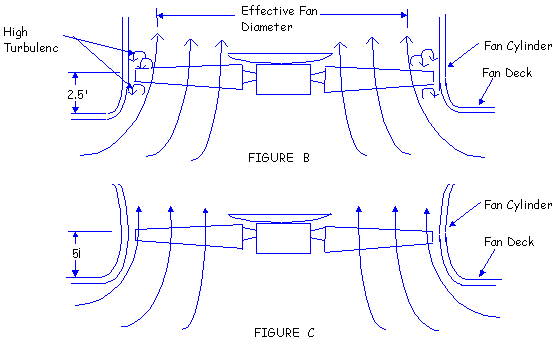
An energy loss occurs as the fan blades must turn the air, resulting in further efficiency degradation. Figure B depicts a more common cylinder that is an improvement over the straight-sided cylinder, but is far from optimum. This cylinder only partially recognizes the vena contracta? effect of reducing the effective diameter of the fan disc. The fan tips are operating in the low velocity, high turbulence zone and the angle of attack between the streamlines and fan plane is not vertical.

The ideal cylinder entrance and fan elevation design is shown in Figure C. This inlet produces minimum turbulence and pressure losses by following the natural shape of the discharge jet. The cylinder, in this design, confirms to the flow path that the air is attempting to take as it exits the tower. Note also that this cylinder properly locates the fan plane at a significantly elevated position, assuming that the air streamlines are vertical before they cross the plane of the fan disc.

An example of the relative performance between the optimum cylinder entrance in Figure C and cylinder shown in Figure B helps put the value of careful system design into perspective. A 22 feet diameter cooling tower fan may typically be required to move 700,000 CFM against a pressure drop of 0.40 inch H2O. The CFM required is fixed by the cooling tower thermal duty and is the same regardless of cylinder design. The cooling tower system operation lines assume identical louver, fill, eliminator and plenum configurations - only the cylinders are different. The fan horsepower required to move 700,000 CFM is 119 BHP with the optimum configuration (Figure C) and 136 BHP with the improved, but not ideal design (Figure B). This is an important analysis for the project owner to consider whenever fan cylinder replacement is called for. Not all "modern" fiberglass cylinders allow the fan to perform at peak efficiency. Unless the cylinder manufacturer or the owner has the capability of analyzing the relationship between cylinder and fan design, significant operating savings can be overlooked.

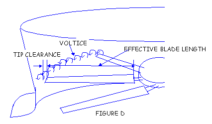
Once the air is properly directed into the cylinder, maintenance of close tip clearance becomes the next consideration. The greater the dimension between the fan tip and the fan cylinder, the less efficient the fan. Space between the fan tip and cylinder allows the creation of air vortices at the blade tips which shorten the effective length of the blade, reducing fan performance. (Figure D)

Close tolerance between the blade tip and fan cylinder minimizes the magnitude of these disturbances, maximizing fan performance. For various, practical reasons, tip clearance must be greater than "zero" to accommodate wind-induced deformation of the cylinder, thermal expansion of the fan blade and the possible build-up of ice inside the cylinder under reverse flow conditions. Tip clearances of two-inch to three inch are not uncommon in cylinders designed without sufficient wind load capability, or without close attention to production and construction details.

The performance difference (in terms of horsepower) of a 22 feet diameter fan with a reasonable tip clearance, is approximately 4.5%. This makes it obvious that the tip clearance of a replacement design is critical. Much of the benefit obtained by utilizing a properly-eased cylinder inlet design can be lost if tip clearance is not rigidly controlled. Excessive tip clearance is usually the result of poor workmanship, poor fit-up, or inadequate structural design.

The next important aspect of good cylinder design is provision for a velocity cone. The addition of the velocity recovery cone to a fan cylinder is in recognition of the fact that the total energy (T) of a moving air stream is constant at all points except for viscous and turbulence losses. Total energy is the sum of the static pressure (Ps) and the velocity pressure (Pv) at a given point. Referring to the fan system shown Figure E, the total energy of the stream immediately above the fan (point 1) is: T1 = Ps1 + Pv1. The total energy at the fan cylinder discharge (point 2) is: T2 = Ps2 + Pv2. If L represents losses due to turbulence and drag between point 1 and point 2, and Ps2 is atmospheric pressure, assumed equal to zero:

T1 = T2 + L
Ps1 + Pv1 = Ps2 + Pv2 + L
Ps1 = (Pv2 - Pv1) + L

Since the velocity cone reduces the velocity of discharge air stream. Pv2 is less than Pv1. This means that relative to atmospheric pressure, the static pressure at a point just above the fan becomes more negative when the recovery cone is added. In other words, the pressure against which the fan operates has been reduced, allowing the fan to move the rated CFM at lower consumed horsepower. The loss (L) keeps the recovery from being complete. A common rule of thumb is that 70% of the difference in velocity pressure (Pv2 - Pv1) is recovered in the recovery cone portion of the cylinders. In actuality, this percentage may vary from 50% to 95%, depending on fan operating conditions.

If a 14 foot high velocity recovery cone is added to the ideal cylinder shown in Figure C, the horsepower required to move 700,000 CFM against 0.40?H2O static pressure is further reduced from 119 BHP to 99 BHP. This represents an additional saving in the power consumption.

An important system consideration sometimes overlooked when increasing fan cylinder height is the impact that the taller stack has on the structure. The taller stack imposes greater dead loads, present a greater projected surface-to-wind loads and has more mass to respond to seismic acceleration. These loads must be handled in a cooling tower structure which may not be equipped with sufficient bracing to accommodate added stress.


2) Effect of Velocity Recovery

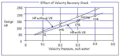
In the case of Wet Cooling Towers, a relatively common means of improving inlet conditions and conserving horsepower is known as a velocity recovery stack. These stacks incorporate a slightly tapered exit cone and a well rounded inlet bell. In theory, there is a significantly reduced velocity pressure at the exit compared to the plane of the fan. Since the quantity of air is the same at both planes, the recovery of velocity pressure is converted into "static regain" which lowers the total pressure requirements of the fan, thus saving horsepower.

Certainly, any axial fan with a velocity pressure of 0.3 inches Aq. or greater can benefit from a fan stack. Below figure shows the effect of fan stack and its potential savings of horsepower from a system efficiency standpoint. Omission of fan stack would be a loss. Note that the fan stack effect is more pronounced at the higher velocity pressures and the horsepower saved at higher flows is very significant. The entrance into V.R. stack through the fan deck should not be ignored as often, it in itself creates turbulence and losses. Although the stack design usually incorporates a generous inlet radius, a sharp corner through the fan deck or heavy structural members beneath can sometimes negate the smooth air flow condition in the stack itself.

The power absorbed by the fan can be reduced by this pressure recovery. Particularly in the case of cooling towers in which the fan velocity pressure is very high in comparison with the static pressure, much attention is directed toward the gradual reduction in air velocity from fan plane to the discharge plane of fan stack. The resultant reduction in the exit air kinetic energy results in substantial power saving.

Basically, Hudson assumes 7 degree of angle per side and an efficiency of recovery of 70%. A poorly designed fan stack is a potential cause of poor air distribution, low fan stack efficiency and significant vibration due to the resonant frequency of fan. For high velocity designs the normal height of fan stack and the diameter of fan ratio is from 0.6 to 1.0.

VP Recovery = Stack Effi. x (VP Fan - VP Stack Top)

where, Stack Efficiency : 70%, VP Fan = Velocity Pressure at Fan

                      Air Velocity                  1
V.P. act. = [ --------------------- ]2 x ----------------------(inch Aq.)
                          4008.7             Density Ratio

(A "4008.7" is a coefficient for converting all the used units to inch water.)

V.P. = (1/2) x (density acceleration of gravity) x V2
= (1/2) x (0.075 lb/ft3 115,820 ft/min2) x V2 (ft/min)2
   (1 lb/ft2 = 0.1922 inch Aq.)
= 0.1922 x (1/2) x (0.075 115,820) x V2
= V2/ 16,069,372.18
= [V/4008.7]2 inch water

                       Airflow Rate (acfm) at Fan
Air Velocity = -------------------------------------------- (ft/min)
                              Net Fan Area

                                 0.075
Density Ratio = ------------------------------
                         Air Density at Fan

VP stack top = Velocity Pressure at stack top

             Air Velocity                 1
V.P. =[ --------------------- ]2 x ---------------------- (inch Aq.)
                 4008.7             Density Ratio

                               0.0750
Density Ratio = -------------------------
                         Exit Air Density

                       Airflow Rate (acfm) at Stack Top
Air Velocity = ------------------------------------------------------ (ft/min)
                                    Stack Top Area

Fan Stack Top Diameter = Fan Diameter + [ 2 x (Tan 7o x Venturi Height) ]

Fan Stack Top Area = (pie/4) x {(Stack Top Diameter)2 }

Net Fan Stack Top Area = (pie/4) x {(Stack Top Diameter)2 - (Seal Disc)2}

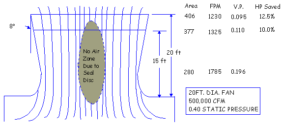
(Note: Hudson is not considering the no air flow zone at the top stack due to the seal disc. Refer to figure shown in the paragraph of Flow Pattern. Unless the height of fan stack is as mush as the fan diameter the fan stack top area must subtract the area of seal disc in the fan.)

Venturi Height = Height from fan plane to top of stack

Suppose airflow volume is 1,063,126 acfm, fan diameter is 28 feet, the height of venturi is 6.0 ft, and air density at fan inlet is 0.0688 lb/ft3. What is the velocity recovery?

                                                      ACFM
Velocity at fan = -------------------------------------------------------------------------
                            (pie/4) x (Fan Diameter2 - Seal Disc Diameter2)
            1,063,126
= ---------------------------------- = 1,853.71 FPM
   (pie/4) x (282 - 7.3332)

                        1,853.71        0.0688
V.P. at fan = [--------------]2 x ------------- = 0.1963" Aq.
                      4,008. 7          0.0750

Fan Stack Top Diameter = 28' + 2 x (0.12278 x 6.0) = 29.47 ft
Fan Stack Top Area = (pie/4) x 29.472= 682.1 ft2

                                              ACFM               1,063,126
Velocity at stack top = ---------------------------- = ----------------- = 1,558.60 fpm
                                        Stack Top Area         682.1

                                   1,558.60          0.0688
V.P. at stack top = [ --------------- ]2 x ------------- = 0.1387" Aq.
                                   4,008.7           0.0750

Acc'ly. the velocity recovery = 0.7 x (VP fan - VP stack) = 0.7 x (0.1963 - 0.1387)
= 0.0403" Aq.

While, the velocity recovery in case of considering the dead zone in the top stack is 0.0271" H2O. (Net fan stack top area: 640.03 ft2, velocity pressure at stack top: 0.1576") The difference in the static pressure gain affects directly the deviation in the fan brake horsepower. In case of this particular sample job (0.4825" Aq. of static pressure), the fan brake horsepower per Hudson fan rating sheet is smaller than one per above normal procedure by 3.1 HP. Of course, the velocity recovery can be varied person by person since the efficiency of fan stack, the angle of fan stack and fan tip clearance, etc. can differ from above. So, we recommend to use your own procedure in calculating the velocity recovery. In general, there is no need to input the value of venturi height to the fan rating program if the venturi height was actually considered at thermal design stage. Note that there are some differences in calculating the velocity recovery between Hudson and our conception. For your information, the actual total pressure could be expressed as follows;

Actual Total Pressure = Act. Static Press. + Act. Velocity Press. - Velocity Recovery (inch Aq.)

3) Flow Pattern

The below figure shows pictorially the flow condition which exist through the fan and recovery stack. Note the very streamlined flow which would be possible with a fully faired hub, and the actual flow around a typical hub seal. The information given in below figure is for a no wind condition. If a 15 MPH wind will give the discharged air an angle of about 45o and cause flow separation on the upwind side of the stack. Under this condition the velocity pressure recovery may be practically nullified.