1) General

When a body or system is given with an initial displacement from its equilibrium position and is released, it will vibrate with a definite frequency called as the natural frequency. In other word, if you were to suspend a slender article and you begin vibrating it at varying frequencies, beginning at zero hz or at some point it would begin to vibrate dramatically as its resonant frequency (RF) was reached. This is a point where its natural frequency to vibrate was exited by an equal applied source and it would resonate.

This is a characteristic of any mass but we are discussing fan blades of any size or type. Additionally, the resonant frequency of an operating fan will be somewhat higher than the measured static natural frequency because of the stiffening effect of centrifugal force. Hudson provides first and second modes of blade natural frequencies. These first mode & second mode resonant frequencies were actually measured on a special vibration mount by a real time analyzer for recording and obtaining them.

2) Fan Dynamic Characteristics

Cooling tower fans for the electric utility and petrochemical process industries are used in sizes varying from 12 ft to 60 ft in diameter of cooling tower, with common fan sizes in the 26-30 ft range. Because fan efficiency has become a significant factor in evaluating cooling tower costs, the larger, more efficient fans are usually selected in new applications, often without sufficient regard to such an important factor as fan dynamic response at low speeds.

Also, the fan's low operating speeds require special and often unfamiliar equipment for analysis and monitoring. Adherence to a few basic rules during fan selection can greatly reduce this dynamic response and associated fan stresses. Implementation of a regular maintenance program based on vibration trend analysis is also imperative to enable scheduling of preventive maintenance and balancing activities. If a failure is imminent, electronic monitoring devices that respond over an extended frequency spectrum can give warning before severe damages is done to the tower or the fan.

To ensure the optimum operating condition of cooling tower fans there are several important things for operating frequencies and resonant frequency margin which have to be carefully considered. Investigation into the dynamic response of a fan blade begins with the determination of the static natural frequency (fs)of the blade. This value can be easily determined for the first mode of vibration by striking the blade and then recording this frequency with a vibration meter. To correct for the effects of centrifugal forces at fan operating speed, this static natural frequency must be converted to dynamic natural frequency (fd). This is done by using the following equation; fd = {(fs)2 + K x RPM}1/2, where fs and fd are both expressed in cycles/min. and K is a constant, whose value is 1.5 for most fans.

For most large diameter cooling tower fans the first mode dynamic natural blade frequency is usually much higher than the allowable operational speed of the fan. Limits on fan speed are governed by blade stress and fan noise. This limit is generally considered to be the speed at which blade tip velocity is 12,000 ft/min. Thus, it is rare to find a cooling tower fan speed that is coincident with its blades' first dynamic natural frequency.

There are two fan operating frequencies which should be separated from the natural frequency of blade in order to avoid resonance at fan. If the force or displacement is applied with a frequency close to the natural frequency of the system, the amplitude of vibration in a system becomes extremely large. This force or displacement is resonance.

As you can see from the definition of the resonance, the vibration amplitude becomes very large as a typical symptom. It is often misunderstood as a fan unbalance problem if there is no vibration analysis capability. However, the resonance problem is a far more dangerous and complex, and the cure can be very expensive requiring either change the motor speed or add blade number.

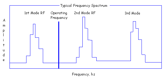
(1) Typical Natural Frequency Spectrum: The peak of natural frequencies on blades are very narrow (2 or 3 hz) due to the fiberglass composite structure requiring less separation than the metal (Aluminum) construction blades. Typical natural frequency spectrum normally follows a signature as below.

As the operating frequency gets close to the center of natural frequency mode, the dynamic stiffness of asystem rapidly decrease compare to the static structural stiffness. This causes the high vibration amplitude. Considering the peak profile characteristics of natural frequency modes and the past experiences, we feel that the minimum separation of 10% away from any natural frequencies is desirable.

(2) Fan Operating Frequencies

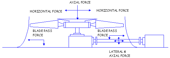
(a) Blade Pass Frequency (BPF): Vibrations that are significant to the cooling tower structure are those thatare induced as multiples of the fan operational speed. These impulse forces or excitation frequencies are functions of the number and order of location of the supporting structures underlying the fan. The basic structural excitation frequency is commonly referred to as the blade pass frequency (BPF) and is calculated by this equation:

BPF = No. of Blades x Fan rpm / 60 (hz)

This is the frequency where the blades aerodynamically excites the supporting beam or tower structure. If a resonance occurs at this frequency, large vibration will be exhibited at the tower structure. The natural frequency of your tower structures should be away from this frequency. This can be a great destruction of fan blades when the blade passing frequency equals the resonant frequency.

The frequency of blade vibration may differ from the BPF if large beams, drive shaft or other obstructions are within about 2 feet from blades. In this case BPF shall be modified by "N" times obstruction. Such as two beams close to the tops may cause a frequency of (2 x BPF) hz. This frequency would have to be compared to the blade's resonant frequency of an exciting force is in harmony with the fan dynamic frequency. Aerodynamic forces generated by blades passing over structural members, lubrication lines, drive shafts, etc. will excite blade vibration at a frequency determined by the number of times per revolution blades pass over obstructions. These critical speed occurs at 2, 3, 4...N cycles per revolution frequency depending on the number of obstructions.

Best results will be obtained if this basic excitation frequency is kept at least three times as high as the fan blade natural dynamic frequency. Equally importance is the associated components of the cooling tower, such as drivelines, fan stacks, beams, etc. which must be tuned to avoid resonance with this basic BPF.

Problems encountered with BPF resonance are usually destructive, and merit immediate attention. One solution is to change the natural frequency response of the components or blades, another is to change the BPF. Changing the BPF can be done by varying either the fan speed or the blade number. Because the later solution involves considerable expense in fan or gear change out, the more practical solution is usually to tune and damp the tower structure by bracing or weighting the individual components. This will help control vibrations induced by the fan relative to the structure.

While necessary to prevent structural problems, measurement of vibration levels on the cooling tower structures tells little about the fan blade itself and its position in the air it is moving. For this reason, wave front analysis techniques have been developed that use telemetry systems to provide stress and acceleration data from the blades as they transit the throat of the fan stack. Frequency spectrum or signature analysis of these data has consistently revealed that these fans experience impulses at all fundamental harmonics of the operating speed.

These excitation forces are created by wave front in the air flow due to the structural patterns found in the plenum directly below the fan. Structural obstructions include wood, concrete, or steel beams, piping conduit, and wind walls.

The effect obstructions have on the air flow is to create dead spots or wave fronts where the air direction is changed or is turbulent. These wave front occur in mathematical series similar to the geometric patterns of the obstructions creating them. As a fan blade makes a revolution, it encounters air loading impulses - excitation forces - in a periodic function that can constitute integral multiples of the operating speed. Therefore, the fan blade's natural dynamic frequency (fd) must not coincide with any multiple of fan rpm.

When selecting fan operational speed it is also important to consider the expected variance in the dynamic natural frequency from blade to blade. If, for example, 28 ft diameter blade's natural frequency were to vary +/- 4%, the possibility of encountering a critical frequency situation is significant. Note that the excitation frequency responses at integral multiples of fan rpm can greatly restrict the speeds at which the blade can operate given the variance in its natural dynamic frequency.

Good engineering practice dictates that these potential driving forces at integral multiples of rpm be kept at a critical range of at least 10% away from the natural frequencies of the fan blades, to avoid resonant amplifications of forces. Because the fan must avoid all multiples of fan rpm, the critical range should be calculated for (N = 1, 2, 3, ...) using this equation: CR = (N x RPM - fd) / rpm x 100.

Due to these dynamic characteristics, large diameter cooling tower fans are not suitable for variable speed service. Programs that attempt to conserve energy by proposing that fans be driven at variable speeds run the risk of encountering severe vibration problems. In such an installation, the cooling tower's plenum chamber would have to be relatively free of flow disruptive structures. Fan blades with high damping factors would also be required, to resist the amplification of forces.

If conservation of fan energy is required, the best approach is use of a two speed electric motor. This will provide no problem, because fans that are operating at full speed in safe critical frequency ranges will automatically be in the same ranges at half speed. Variable pitch fans are also an acceptable method of controlling fan flow and energy, and this is the method that is recommended in cases where a precise level of fan throttling is needed.

(b) Beam Pass Frequency: This is the frequency where the aerodynamic effect of the beam occurs to fan blade and is obtained from an equation of Beam Pass Frequency = No. of Beam x Fan rpm / 60 (hz). If a resonance occurs at this frequency, the blade might be damaged at its mode(s) depending on the mode type (i.e. first or second mode) where the excitement force coincides at. In normal cases, this frequency is less important since the RF margin exceed the minimum 5%, but there is often a case to carefully consider the RF margin in case of small number of fan blades.


3) Critical Speed

The critical speed can be calculated by the following equation:

                                            1st Mode RF x 60
1st Mode Critical Speed = ----------------------- (rpm)
                                            Number of Blade

                                             2nd Mode RF x 60
2nd Mode Critical Speed = ------------------------ (rpm)
                                             Number of Blade

For example, fan diameter = 28 ft and number of blade = 9,

1st mode critical speed = 6.3 x 60 / 9 = 42.0 rpm.
(1st mode RF of 28 ft - 9 = 6.3 hz)

(Note that the 2nd mode RF do not need to consider.)

4) Resonant Frequency Margins

A first resonant peak ideally should not occur between "0" hz and the fans operating speed. If one does occur during acceleration from rest, it will show up only as a momentary "shudder", since most of fans reach full speed within 3 seconds or less. In case of variable speed drive however, a resonant peak between "0" and the operating speed presents a real problem. The fan must be prevented from running steady state at or near the resonance speed by means of an electronic lock-out of a narrow speed range.

In most cases, there is not necessary to consider the first critical speed and only to carefully consider the second critical speed. Typically, we recommend minimum 5% of RF separation between the first mode RF frequency and the blade passing frequency, or between the first mode RF frequency and the beam passing frequency. In any cases, beam passing and blade passing frequencies could not occur within the + 5% to - 5% of any RF modes. This is most important requirement in sizing a fan. (Note that the beam passing frequency consideration is not required for the steel or wood structure having the narrow beams.)

(1) RF Margin with Blade Passing Freq.: The formulations must be differently applied to obtain the RF Margin per the value in difference of first mode RF and blade passing frequency as follows;

Case I : First Mode RF > = Blade Passing Frequency

                       First Mode RF - Blade Passing Freq.
RF margin = ------------------------------------------------ x 100 (%)
                                     First Mode RF

Case II : Blade Passing Frequency >= First Mode RF

                       Blade Passing Freq. - First Mode RF
RF margin = ------------------------------------------------- x 100 (%)
                                     First Mode RF

(2) RF Margin with Beam Passing Freq.

Case III : First Mode RF > = Beam Passing Frequency

                       First Mode RF - Beam Passing Freq.
RF margin = ------------------------------------------------- x 100 (%)
                                    First Mode RF

Case IV : Beam Passing Frequency >= First Mode RF

                       Beam Passing Freq. - First Mode RF
RF margin = ------------------------------------------------- x 100 (%)
                                     First Mode RF

(3) Adjustment of RF Margin: The first mode RF is a fixed value as per the fan size & no. of blade. Only a choice for deciding this margin depends on the factor of blade passing frequency.

For increasing the RF margin it is required up or down the blade passing frequency with the adjustment of fan speed or number of fan blades. In case that the first mode RF is smaller than the blade passing frequency. (Case II), it is necessary to increase the blade passing frequency. This is very simple.

In opposite case that the first mode RF is larger than the blade passing frequency (Case I), in order to reduce the blade passing frequency it is required to decrease the fan speed or to decrease the number of fan blades. Lowering the number of blades or decreasing the fan speed, it could be another problem, which might exceed the maximum brake horse power per blade or which might be a considerable increase of brake horsepower of fan due to less number of blade.

Normally, we recommend that the fan bhp per blade must lower than the maximum bhp per blade by 4 bhp, since the fan blade of fiberglass composite may be damaged due to over torque. Especially if you did not consider the wind velocity surrounding the cooling tower at the initial fan design, it is necessary to have more margin for the maximum bhp/blade since fan bhp per blade might exceed considerably the maximum bhp/blade due to increase of airflow volume and static pressure due to wind velocity.

There is still a problem to decrease the number of blade. In reducing the fan rpm the fan pitch will be increased and the fan bhp will increase, too. Therefore, the problem is still same as reducing number of blades. So, you are required to increase the fan diameter.

Meantime, it is not simple to control the beam passing frequency since number of supporting beam is almost fixed and could not be adjusted. Only a choice is to increase or decrease the fan speed with the gear reducer.

For increasing the RF margin it is required up or down the beam passing frequency with the adjustment of fan speed. In case that the first mode RF is smaller than the beam passing freq., (Case IV), it is necessary to increase the fan speed in order to increase the blade passing frequency.

In opposite case that the first mode RF is larger than the beam passing freq. (Case III), in order to reduce the beam passing frequency it is required to decrease the fan speed. In case of decreasing the fan speed, it could be another problem as mentioned previously.

(4) Blade Harmonic Constants: The potential for magnification of forces when a critical range (resonance) is zero is very great, and depends on definition of harmonic constants and damping factors. The harmonic constant (KH) is a factor that is a function of wavefront conditions: it describes the potential of a blade to resonate in the harmonic situation (N = 2, 3, 4, ...) relative to an N = 1 first order response. The amplification factor (AF) of the blade can be calculated by: AF = KH + {[1 - (N x rpm/fd)2]2 + [2 z x (N x rpm/fd)]2}1/2, where the damping factor z = ln [x/(x + 1)] and x is the amplitude. At resonance, the frequency ratio N x rpm/fd equals 1, and the magnification factor (MF) by substitution into the above equation is: MF = KH/2 z.

Damping factors typically range from about 0.012 for metal blades to 0.036 for foam filled fiberglass polyester blades. The harmonic constants have been estimated to range from 0.24 to 1.0. Critical range and potential of the system should be investigated at fan installations where breakdowns are consistent or occur early in operating life. If it is determined that the system is approaching a critical range of operation, several remedies are possible. The easiest solution may be to disrupt the air-impulse excitation frequencies through removal or rearrangement of obstructions in the plenum. This will lower the harmonic constant of the tower, but can never remove all amplification potential.

A more positive method is to change the dynamic natural frequency of fan and move it out of critical range. This can be done either by changing the speed of the fan or by weighting the blades to change the natural frequency. In most cases, weighting the blades proves to be the more economical solution to the problem.

(5) Relation with Cooling Tower Structure and Blade Passing Frequency: In a cooling tower, air is moving over obstruction or beams blocked inlets, etc. It could mean a possible interaction in the structure or fan stack with blade passing frequency. Note that Hudson does not cover the frequency interaction in a cooling tower structure besides supporting beams since they are beyond fan maker's control. This interaction between the operating frequency and tower itself (i.e. blade passing frequency interaction with fan stack natural frequency) could be suited by tower manufacturer to avoid the resonant problem at tower.

In the application of wood structure tower and FRP fan stack, a special attention is required. To avoid the running of fan in the tower structure resonance and to control the vibration with the 80 microns at the gear reducer or the motor frame, the number of blades have to be carefully selected. For your information, 6 mils (1 mil = 0.001" = 25.4m, peak to peak) is the maximum vibration allowed on Air Cooled Heat Exchangers specifications. So, Hudson has adopted API spec. of 6 mils for gear reducers on cooling tower structures. It has been realistic for US constructed wooden towers.

This is to be considered a maximum limit on the gear reducer itself not a normal level. Common practice in US is to use the minimum recommended number of blades to reduce the vibration in the wood structure tower and FRP fan stack. This is to avoid dangerous air load induced pulsation on the fan cylinder. The fewer blades are occurring the higher air loads and are enlarging the more intense blade passing pulsation.

If you ask to guarantee the levels as low as 3 mils (0.003" = 76.2 microns), the dynamic field balancing would be required for the fans. Of course, the number of blades must be increased from the minimum number of blades (described in Chapter 1 ) at 80 microns or less requirement of vibration. To achieve the vibration limit on the wood structure tower and FRP fan stack, a check of frequencies must be done that there are no tower resonance at the blade passing frequency or 1 x fan rpm 60 frequency. While the concrete tower are so structurally stiff. So, fan vibration is rarely a problem.

If a vibration problem occurs in the field there are several options to correct the problem: First, you have to analyze the amplitude versa frequency for positively determining the problem. You are required to plot them via a vibration analyzer. This shows immediately amount of vibration and its frequency which tells where the vibration occurs. If the vibration occurs at the fan blade passing frequencies, the tower structures is in resonance with the fan blade passing frequency. This is not a problem of fan balance. It is very difficult to stiffen a wooden structure of fan stack. Most of time, to increase the number of blade is the least costly solution. But, if the problem was occurring at 1 x fan rpm / 60 (hz), this problem is due to the unbalance of fan assembly, which must be corrected properly by fan maker.

Meantime, you can easily understand that the fan stack is in resonance with fan blade passing frequency if you remove the fan stack (if the materials of fan stack is made of FRP) and run the fans at the rated rpm. Unless the problem is in 1 x fan rpm / 60 (hz), it's not a problem of fan balance. [If you consider the total unbalance as a vector (weight at some distance), it moves out of the plane of rotation only one time per revolution. Hence, 1 x fan rpm / 60 (hz) equals fan unbalance.] In general, the unbalance of fan could be corrected per below actions.

  • Minimize tip track variation which is a major source of dynamic imbalance.
  • Check the proper assembly of fan including hardware tightness, blades in the proper position, and blades at the equal pitch.
  • Balance the fan "in place"
    (Note: "In place" balancing is effective because it takes the mass of the existing machinery mount and dynamic imbalance into consideration.)
  • Change the fan blades or entire fan.

5) Fan Vibration Monitoring

A cooling tower fan is a rotating machine subject to the same laws of physics as any other. Cooling tower fans have three qualities that make dealing with them a special challenge. These qualities are 1) wet and corrosive environment, 2) slow rotational speeds, and 3) a wide range of support structure rigidity.

The basic fundamentals of vibrations are 1) All machines vibrate. 2) Vibration is caused by forces generated by rotation, reciprocation and impacts. 3)Vibration frequency equals rotational or reciprocating speed and multiples or repetition rate of impacts. 4) Many machine faults produce vibratory forces as follows;

  • Unbalance at one time RPM.
  • Aerodynamic unbalance at number of blades times RPM
  • Misalignment at one, two and three times RPM
  • Looseness at two times RPM
  • Gear Faults at number of teeth times RPM
  • Faulty rolling element bearings at RPM multiples

It is not the vibration that is harmful. Vibration is the symptom of the presence of vibratory forces and the mechanical faults that cause them. Forces cause wear and destruction not vibration. This view of vibration is most important when related to rotating machinery maintenance. From this viewpoint there are no vibration problems. There are mechanical problems that reveal their presence by the way they cause the machine to vibrate. Correct the mechanical problem and the symptom, vibration, will go away.

A typical cooling tower fan arrangement consisting of drive motor, drive shaft, gear reducer, and the fan. The fan normally rotates slowly, is multi bladed, with high tip speeds. The support structure may be wood, concrete or steel and not as stiff as the designer would like because of compromises made in favor of unrestricted air flow. The environment is usually highly corrosive and wet. This means most materials will deteriorate in time, producing a variety of problems.


A survey of a number of cooling tower fan operators and some vibration specialists revealed that the gear reducers are the most common mechanical problem. Most electrical problems were next, followed by motor drive shaft-gear reducer misalignment. Drive shaft unbalance, poor fan blade adjustment, bearing problems and occasionally fan unbalance and structural resonance complete the list. All of these problems produce vibration that can be used to detect the problem and what the problem is. An unbalance problem of fan is very rare. These few were out of balance because blade tip drain holes were plugged. The below table summarizes the problems, and the symptomatic vibration frequency and amplitude of each.

Cause

Frequency

Amplitude Normal to Max.

Clues

Gears

Number of Teeth X rpm

0.15 to 0.6 in/sec

Harmonic

Electric Motors

Synchronous

0.1 to 0.6 in/sec

Beats

Drive Shaft
- Alignment
- Unbalance


1 & 2 x rpm
1 x rpm


0.1 to 0.6 in/sec
0.1 to 0.6 in/sec


Axial
Radial

Fan Unbalance

1 x rpm

5 to 50 mils

@ Gear Box

Fan Blade Adjustment

1 x rpm & Multiples

5 to 50 mils


Resonance

Fan rpm & Multiples

Larger than Normal


Vibration amplitudes are affected considerably by support rigidity which makes it extremely difficult to establish vibration standards. Be sure to coincide support rigidity when using any of available limits. Most of them were established for fairly stiff supports. The normal to maximum amplitude presented may be used as guidelines when manufacturers limits are not available.

Which parameters should be used, displacement, velocity or acceleration? The motion of an oscillating part can be described by its amplitude in terms of displacement (mils or microns, peak to peak), velocity (in/second or mm/second peak) or acceleration (g) and its frequency. In general, it has been used to refer to displacement as peak to peak (i.e. double amplitude) while velocity and acceleration are peak (i.e. single amplitude).

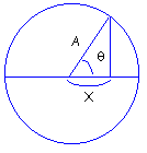
Displacement, velocity and acceleration are related to each other by frequency.

X = A Cos q
V = dX/dt = d(A Cos q)/dt = A w Sin q, Vmax occurs where Sin q = 1

Therefore,
Vpk = A w = A x (2pf) = (Disp./2) x 2 pf = pf Disp. (Double Amplitude)
= 3.1416 (CPM/60)(1 inch/1000)
= 52.36 x 10 -6 mils.CPM

Disp.= Vpk / pf = (1/p)(Vpk/f) = 0.3183 (Vpk/f)

a = dV/dt = d(A w Sin q)/dt = d(A 2pf Sin q)/dt = 2pf V ( - Cos q), apk = 2 pf V ( -1)
[The (-) means that g is 180 deg. out of peak with disp.]

G = a / 386.1 = 2pfV / 386.1 = 0.0162 fV (in/second2)

(1) Vibration in Cooling Tower: A cooling tower contains essentially 3 pieces of rotating machinery - the motor, the gear reducer and the fan. The primary forces which would cause an increase in vibration level include;

  • The vibration of the fan and fan shaft is caused by the fan unbalance (1 x rpm), blade pass frequency (number of blades x rpm), fan shaft misalignment (2 x shaft rpm), fan bearings (more than 10 x shaft rpm)
  • The motor and drive shaft i.e. motor or drive shaft unbalance (1 x drive shaft rpm) or misalignment (2 x drive shaft rpm)
  • The gear reducer itself - bearings (more than 10 x shaft rpm), gear mesh (number of teeth x rpm)

Of course, if there is a blade resonance or structural resonance which corresponds to one of the frequencies noted above, then a relatively small force can create a high vibration. In this case, since there is almost always some unbalance and misalignment present, the problem would be the presence of a resonance rather than too much unbalance, etc. In either case, of course, the electronic switch would trip.

(2) Location and Number of Vibration Switches: Most often only one switch is used. However, some customers use two, one on the motor and one on the gear reducer. When only one switch is used, the preferred location is on the side of the gear reducer. Since Vibration Switches measure the vibrations perpendicular to its base, the advantage of this location is that we will be sensing the radial vibration from both the fan shaft and the coupling shaft.

The vibration switch will then sense the vibration resulting from unbalance and misalignment of fan shaft and blade pass frequency, plus unbalance and misalignment of the coupling shaft. (Since these potential faults generates vibrations at different frequencies, it is essential that the switch trip on vibration velocity.) Further, protection is also afforded in the gear reducer itself.

In the past, some cooling tower manufacturers have mounted the switches on the motor rather than the gear reducer. This will protect for motor and coupling shaft unbalance. On wooden structures which are relatively soft, a severe fan unbalance may be sensed at this location (i.e. severe damage may result before a trip occurs) and affords no protections for the gear reducer. However, with a concrete structure, it is unlikely that fan vibrations would be sensed at the motor location.

The motor location was chosen for convenience when only mechanical type vibration switches were available. These required reset to be accomplished with a reset button on the vibration switch itself and it was inconvenient to get to the gear reducer to accomplish reset. Since the electronic type of vibration switches provide the capability for latching the trip and remote reset, when a trip occurs, it is not necessary to get to the gear reducer in order to reset the switch. A reset button could be located at the motor platform or other convenient location.

(3) Benefits of Electronic Switches over Mechanical Switches: Historically, users have specified mechanical vibration switches (like Murphy VS-2EX series vibration switches) because there have not been alternative and the limitations of mechanical switches have not been widely disseminated. The electronic switch has been in use for several years but is still not widely known. The mechanical switch is relatively cheap but is relatively ineffective and undependable. There are several fundamental reasons for this resulting from the inherent limitations of mechanical switch. Yet strangely, acceleration switches are used on many cooling tower fans. They may be effective with severe gear problems but not for drive shaft misalignment and unbalance or fan unbalance. A velocity sensitive device is appropriate for gear reducers. A careful look at how each type device operates and performs may help you to understand its capabilities and make the proper choice for his equipment protection needs.

Many large diameter cooling tower fans have inadequate vibration cutout devices. Devices designed for other applications, such as mechanical inertia spring or magnetic release - switches are often in use. Cooling tower fans up to 30 feet in diameter should have a system that can respond in a linear manner to preset vibration severity levels over a frequency range from 120 to 30,000 cycles per minute. Provisions for a time delay to avoid start-up trip out are also important.

These requirements are beyond the capability of most mechanical devices. Such devices set to trip on one frequency range may not respond to low frequency vibrations. It is also common to find that in order to prevent them from tripping out on startup, mechanical devices are set so high or are so remotely located as to be ineffective. Mechanical devices are also of no use in establishing monitoring systems.

Mechanical Vibration Switch, by its nature is acceleration sensitive. In principle a magnet exerts a pulling force on a weighted arm. This force is opposed by an adjustable spring by which the operator sets the trigger level-the greater the spring force, the less the acceleration force required to overcome the spring. When the acceleration force exceeds the magnetic force, the latching magnet pulls in the arm and mechanical relay is thus closed, proving the alarm or shutdown.

Electronic vibration devices that monitor vibration levels based on velocity measurements are available to meet requirements of large diameter cooling tower fans. However, a careful examination of their frequency response is required to assure protection at the large fan's lower operating speeds. Fans larger than 30 ft operate at speeds that are below the useful range of most velocity-limiting systems. These larger fans should have a system that reacts to displacement measurements to monitor fan conditions. Systems based on proximity sensors are best suited for this application.

Electronic Vibration Switch consists of a solid state crystal which produces electrons when it is deformed by the acceleration force. This electrical output is electrically integrated, producing a signal proportional to velocity. This signal is then compared with a preset limit and triggles a triac (in effect a solid state relay) if the level has been exceeded. This relay closure can be used by the customer to alarm, shutdown, etc. Thus it is a completely solid state, self contained unit. The customer need only bring 110 V power leads to it and bring leads to the relay.

Inputs from major users are that the mechanical switch frequently triggers when it shouldn't during its youth, and may not trigger at all after it has been installed for some time. (One year after installation.) Very frequently the user has jumpered them out. In short, as a protection device, they're very questionable indeed! Why?

  • They are mechanical and subject to corrosion, dirt, etc. (The electronic unit is all electronic - no moving parts.)
  • The mechanical construction is a very undesirable approach from a vibration viewpoint - the cantilevered beam, mass, and springs are subject to resonance being excited by higher frequency machinery vibration (which may be one reason for spurious triggering.)
  • The mechanical switch triggers proportional to acceleration. Damage potential is proportional to velocity in the speed ranges of most rotating machinery. The damage potential to your auto is very high at 60 MPH and zero acceleration. Likewise one could have a very high acceleration from 0 to 5 MPH but the damage potential would be relatively low at this low velocity.
    Further, acceleration increases linearly with frequency (RPM) as compared to velocity. Thus, the amount of protection depends on frequency and the device gives too much protection at some frequencies and not enough at others.
  • The accuracy of the triggering point is very poor with the mechanical switch - +/- 5% of full scale. Full scale for the mechanical switch is 4.5g which means accuracy is +/- 0.22g. This is a Catch 22, because typically desired limit levels are around 0.2g. So in this case triggering theoretically could occur anywhere from zero to 0.4g - very poor by anyone's standards. (The electronic switch is +/- 10% of set point, i.e. set at 0.2 in/sec velocity, triggering will occur at 0.2 +/-0.02.>

The solid state of electronic vibration switch has many advantages over the older mechanical design as follows;

  • Electronic switch uses a crystal to generate and electrical output to sense vibration level. No moving parts to wear or resonate. By contrast the mechanical switch uses magnets and springs to sense the vibration.
  • Built-in field adjustable time delay to avoid trip on high start-up vibrations or from transient vibrations during normal running. Mechanical switches do not have time delay. Consequently, trip points are frequently set so high that no protection is provided.
  • Trips on velocity rather than acceleration. The mechanical switch can trip only on acceleration. All authorities in the field agree that damage potential is related to vibration velocity. Acceleration trip provides over protection to fault which generate high frequency vibrations (i.e. false trip) and under protection to low frequency problem (i.e. they do not trip when a low frequency fault occurs.).
  • Calibrated setpoint dial. Permits setting trip level to known value in engineering units of in/sec. The user never knows where the mechanical switch has been set, or if it has been re adjusted by an unauthorized person.
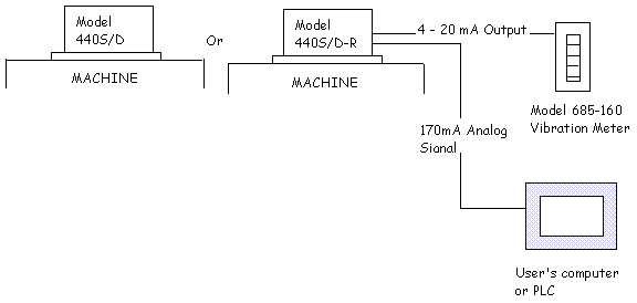
  • Many options are available with the electronic switches that are not possible with the mechanical type switch including: separate transducer, dual trip settings and 4-20 mA analog output.

(4) Layout of Vibration Switch Arrangement

(A) Direct Mounting or With Remote Readout Option

(B) Remote Transducer Option or With Remote Readout Option or Remote Control