|
1) Hub Series
Hudson Tuf-Lite II fan having
a T-H blades has a unique range of bushing type and
hub series as follows;
| Hub
Series |
Range
of Fan Dia. |
Available
Spool Type |
| 3000H |
7
- 14 feet |
no
bushing, Q-2, R-2,3957 Spool |
| 4000H |
16
- 20 feet |
no
bushing, R-2, S-2,5803, 5754 or 5912 Spool |
| 5000H |
22
- 30 feet |
no
bushing, R-2, S-2, U-1, 5803, 5754 or 5912 Spool |
2) Bushing
The bushings are mounted
in the space between the hub and shaft of gear reducer,
and it protects the fan slide down in the straight shaft.
Hudson uses a different type of bushing in accordance
with the size of shaft diameter, and there are various
kinds of bushing. The bushing is supplied by Hudson
together with fan assemblies. We recommend to use the
bushing whenever a US sized shaft of gear reducer is
consider due to the following reasons:
- ● The metric spool machining
charge is avoided.
- ● It is far easier to install
and remove the hub from the shaft.
The tolerance of standard
bushing bore (+0.003" / -0.000") is normally
larger than the machined spool bore by three times.
The bushing has actually a tapered split (two), which
will allow the bushing to lock in to the shaft. So,
a close tolerance such as the straight spool bore is
not required. The below is a typical hub drawing.
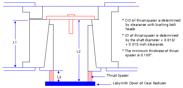
Some clearance between the
top retaining plate and the shaft is recommended to
allow a clamping force between both parts. Typically,
minimum of 0.25" is recommended. Typical shaft
engagement in the bushing assembly up to a full bushing
length is Hudson? standard. Also, the clearance between
the retaining plate and the wall of bore or the hub
plate is recommended. Typically, minimum of 0.25"
is recommended, too.
The limitation of maximum
bore size for each bushing are as follows.
| Bushing
Type |
Up
to Bore |
| Q-2 |
2-5/8" |
| R-2 |
3-5/8" |
| S-2 |
4-3/16" |
| U-1 |
5" |
3) Metric Hub Spool for 3000
& 4000/5000 Series
This spool is used to 7 feet
thru 32 feet diameter fan having a metric size of bore.
The gear shaft/hub engagement must be larger than 1
times gear shaft diameter for sure. Generally, a top
retaining plate is not used on straight shaft since
all hoods are down and straight bore spools have two
large set screws at 90 to secure the shaft. The shaft
thrust spacers must be used to straight bore for protecting
the slip of fan due to the loose of set screws.
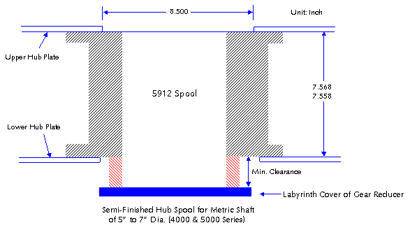
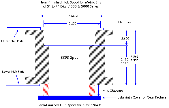
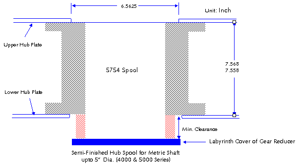
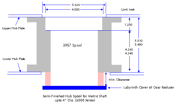
The limitation of maximum
bore size for each bushing are as follows.
| Spool
Type |
Up
to Bore |
| 3957
Spool |
4" |
| 5803
Spool |
5" |
| 5754
Spool |
5" |
| 5912
Spool |
7" |
Note that we recommend the
sliding fitting (which is not intended to run freely,
but to move and turn freely and locate accurately.)
between the fan hub and gear shaft in order to avoid
the damage of bearing of gear reducers and to maintenance
or repair the gear reducer. The shrink fitting must
be undesirable. We do not recommend to use "metal
to metal (i.e. shaft =125.000 mm, bore =125.000 mm)"
fitting between the shaft and bore. It is important
to allow for a clearance rather than a interference.
Per ANSI metric clearance fits (ANSI B4.2-1978), the
hub spool is finished and the tolerances by size are
as follows;
|
Basic Size |
Sliding |
| Hole
(G7) |
Shaft
(h6) |
Fit |
|
30 |
Max |
30.028 |
30.000 |
0.041 |
| Min |
30.007 |
29.987 |
0.007 |
|
40 |
Max |
40.034 |
40.000 |
0.050 |
| Min |
40.009 |
39.984 |
0.009 |
|
50 |
Max |
50.034 |
50.000 |
0.050 |
| Min |
50.009 |
49.984 |
0.009 |
|
60 |
Max |
40.040 |
60.000 |
0.059 |
| Min |
60.010 |
59.981 |
0.010 |
|
80 |
Max |
80.040 |
80.000 |
0.059 |
| Min |
80.010 |
79.981 |
0.010 |
|
100 |
Max |
100.047 |
100.000 |
0.069 |
| Min |
100.012 |
99.978 |
0.012 |
|
120 |
Max |
120.047 |
120.000 |
0.069 |
| Min |
120.012 |
119.978 |
0.012 |
|
160 |
Max |
160.054 |
160.000 |
0.079 |
| Min |
160.014 |
159.975 |
0.014 |
4) Top Retaining Plate &
Thrust Spacer
With a means for positively
locking the hub to gear shaft, the hub should be retained
on the top of hub. Especially for deicing in the cold
weather, fan can be run in reverse rotation for short
periods of time to reverse airflow. In that case, there
is a possibility for fan to leave from the shaft. Typically
the reverse speed is limited to the half of rotating
speed, since the air load forces on fan blades are reversed.
The thrust spacer is required
to protect the slide down of fan for the straight shaft
called no shoulder on the output shaft of gear reducer.
The thrust spacer is a merely sleeve that fits loosely
on the shaft to contact the bottom of fan hub and the
top surface of labyrinth cover of gear reducer. It is
strictly a safety one to prevent the damage of fan and
gear reducer in case that the bushing hub slides down
the shaft. Of course, that is very rare, but if it has
happened it is an expensive accident. Such spacers are
not furnished by Hudson, and customer should design
and manufacture this one in accordance with shaft diameter
& key size.
|


