|
5) Sound Power Level
For the quantification of
the noise intensity, and in order to compare one cooling
fan configuration with another, it is at least necessary
to have a relationship between the noise intensity and
important design parameters like pressure drop, flow,
fan speed, and fan diameter. Through years of research
and field measurements Hudson has developed the following
relationship;
Sound Power Level (PWL)
= C + 30 Log(Tip Speed/1000) + 10 Log(hp) - 5 Log (Dia.)
+ f
The characteristic value
C represents the influence of the fan shape on the noise
generating phenomena or as practically said before,
the intensity and quantity of swirls. From formula above
it becomes clear that especially the tip speed has a
strong influence factor on the sound power level. The
correction term f is related to characteristic noise
mechanisms which have been referred to already; the
influence of obstructions like fan supports, the influence
of the flow inlet shape, pitch angle, and tip clearance,
etc. The influence of obstructions both on inlet and
outlet is defined as a function of the swept area of
the obstruction and the area of the fan section.
6) PWL per Octave Bands
The sound spectrum (linear)
can be obtained by adding the correction factors stated
below to PWL dB(A). The correction is independent of
blade passing frequency.
| Octave
Bands (Hz) |
Correction
Factor |
| 31.5
(22.3 to 44.6) |
+
2.0 |
| 63
(44.6 to 88.5) |
+
5.2 |
| 125
(88.5 to 177) |
+
4.0 |
| 250
(177 to 354) |
+
0.9 |
| 500
(354 to 707) |
-
4.5 |
| 1000
(707 to 1414) |
-
4.9 |
| 2000
(1414 to 2830) |
-
10.1 |
| 4000
(2830 to 5650) |
-
12.6 |
| 8000
(5650 to 11300) |
-
19.9 |
In case of PWL = 104.8 dB(A),
the PWL per octave bands are as follows:
| Octave
Bands |
31.5 |
63 |
125 |
250 |
500 |
1K |
2K |
4K |
8K |
| PWL
(dBA) |
106.8 |
110.0 |
108.8 |
105.7 |
100.3 |
99.9 |
94.7 |
92.2 |
84.9 |
7) Sound Pressure Level (SPL)
Acceptable noise levels are
generally specified as a sound pressure level expressed
in decibels (linear) or A-rated decibels (dB(A)), that
may not be exceeded when measured at a certain distance
from the noise generating equipment. The specified distance
may be by the plant boundary or a given noise sensitive
location, such as a residential area.
This SPL is a noise at a
point from the sound source. It is the sound we measure,
while the sound power level can not be measured directly.
Measurements for community noise requirements are made
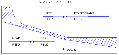
at the plant boundary or nearest residence in the far
field of the cooling tower. The far field is defined
as the region where there is a linear relationship between
the sound pressure level measured and the distance from
the noise source.
In the far field, the sound
pressure level will drop 6 dB with each doubling of
distance. The far field will generally begin at a distance
of four times the largest machine dimension. For instance,
if a cooling tower is 20 ft x 30 ft, then the far field
will begin at 120 ft from the source. In the far field,
the sound pressure level can be calculated by
SPL = PWL - 10 Log (As) +
0.23 (As in ft2 is the surface area over
which noise is radiated.)

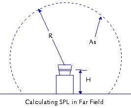
Noise will tend to radiate
from a non-directional source uniformly in all directions.
Sound pressure waves move spherically away from the
source. The radius of this sphere is the distance to
the measurement point. However, if there is a reflective
surface impeding spherical radiation, then the radiation
will become only partially spherical. In this case,
the surface area also depends on the height of the noise
source above the ground. In this case, As = 2pR(R
+ H). If the height goes to zero, the radiation takes
on a hemispherical shape and As = 2pR2.

In plant noise requirements
are generally in the near field of the noise source.
In this region, sound pressure levels are difficult
to predict because of the non-linear relationship between
sound pressure level and distance from the source. Also,
noise sources that are not directional in the far field
may be directional in the near field.
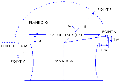
The calculation procedure
specified below can be used in case there is a fan stack
with a minimum height of 0.35 x fan diameter and a maximum
of 1 x fan diameter.

(1) Sound Pressure Level
in Point P = PWL - 2 - 10 Log 2pR2
+ ( - 6.8 (1-(Cos a)0.5))
(Note that this equation could be applied to a case
that the radius R is within the distance of 5 times
the diameter of fan stack top and a is smaller than
90 deg.
(2) Sound Pressure Level
in Point A = PWL - 2 - 10 Log 2pR2
+ (2 - 6.8 (1 - (1/R)0.5))
(3) Sound Pressure Level
in Point B = PWL - 2 - 10 Log 2pDK2
- 4.8 + 4 (1 - R/DK)
(4) Sound Pressure Level
in Point Y = SPL in Point B - 1.5
(5) Sound Pressure Level
in Plane Q - Q = PWL - 2 - Log pDK(DK/4
+ H)
Let's calculate the sound
pressure levels for the example of PWL of one fan is
101 dB(A) and the diameter of fan stack top is 10.119
m.
(1) SPL at Point P: R = 50
meters, a = 87.8,
then SPL = 101 - 2 - 10 Log (2 x 3.1416 x 502)
+ (2 - 6.8 x (1 - Cos 87.80.5) = 53.57 dB(A)
(2) SPL at Point A: R = [(10.119/2
+ 1)2 + 1]0.5 = 6.14146 M
then SPL = 101 - 2 - 10 Log (2 x 3.1416 x 6.141462)
+ (2 - 6.8 x (1 - (1/6.14146)0.5) = 73.20
dB(A)
(3) SPL at Point B: R = (10.119/2)
+ 1.025 = 6.08 M
then SPL = 101 - 2 - 10 Log (2 x 3.1416 x 10.1192)
+ (2 - 6.8) + 4 x (1 - 6.08/10.119) = 67.71 dB(A)
(4) SPL at Point Y: R = 6.08
M, H1 = 0.5 M
then SPL = SPL at Point B - 1.5 = 66.21 dB(A)
(5) SPL at Plane Q - Q: H2
= 1 M
then SPL = 101 - 2 - 10 Log [3.1416 x 10.119 x (10.119/4
+ 1)] = 78.50 dB(A)
(6) SPL at Point of Residence:
This is required to analysis the noise specially.
8) Noise Calculation from
Two or More Noise Sources
From two or more difference
noise levels, the total sound pressure level can be
calculated per the formula of 10 Log (10 0.1 x
SPL1 + 10 0.1 x SPL2 ... + 10 0.2
x SPLn-1 + 10 0.1 x SPLn). This is
very useful to obtain the resultant of different SPL
at a point. For example, if the background noise level
at a point is 53 dB(A) and the noise level due to a
mechanical equipment is 59 dB(A), the total noise level
at a given point is obtained from 10 x Log (10 0.1
x 53 + 10 0.1 x 59) and the result
is 59.97 dB(A).
Also, the noise subtraction
from a noise level can be obtained from a formula of
10 Log (10 0.1 x SPL1 - 10 0.1 x SPL2).
This is frequently used to guess a noise due to mechanical
equipment from a measurement of noise at a point. For
example, when the noise level at a point is 55 dB(A)
and the background noise at that point is 53 dB(A),
let's calculate a noise level due to the mechanical
equipment.
SPL = 10 x Log (10 0.1
x 5.5 - 10 0.1 x 5.3) = 50.67 dB(A).
9) Reduction of Fan Noise
Design is the primary factor
affecting the fan noise. The blade design determines
the pressure capability of the blade. Since the pressure
is proportional to the fan speed squared, added pressure
capability means a fan can run slower and do the same
work. From above equation representing the sound power
level from a fan, it is clear that an approach for achieving
the noise reduction is to look as decreasing the characteristic
value C and/or the tip speed of fan without reducing
the pressure drop, flow, or fan efficiency.
Reduction of the tip speed
of a fan will indeed reduce the noise generated, however
it will also reduce the pressure and flow. The reduction
of pressure and flow can be avoided by making the blades
wider. Wider blades perform aerodynamically the same
as narrow ones, but at lower speed. This is similar
to a sail-plane which can fly at a lower speed than
a motorized plane because of its bigger wing area. The
relative width of the fan blades is expressed by the
total width of the fan blades to the fan circumference
in the so called solidity number.
It is evident that it is
possible to make a significant improvement by making
the fan blades wider. The reduction of noise generation
can be almost totally yet simply explained by the possibility
of reducing the tip speed, which decreases the quantity
and intensity of swirls. This is attributed with a shifting
to the lower frequencies, which is favorable for the
A-weighted noise spectrum.
The application of low noise
fans has an enormous impact on the costs of construction
and performance of cooling towers. The consequences
can be considered from two principle positions.
- ● Avoiding of the application
of sound attenuators: Sound attenuators are expensive
as well as power and space consuming.
- ● Higher loading and performance
of an existing cooling tower: If a certain PWL value
is acceptable for a particular application, then it
is possible to operate the existing tower with a low
noise fan with a much bigger flow than with a standard
fan.
|


