|
A survey of a number of cooling tower fan operators
and some vibration specialists revealed that the gear
reducers are the most common mechanical problem. Most
electrical problems were next, followed by motor drive
shaft-gear reducer misalignment. Drive shaft unbalance,
poor fan blade adjustment, bearing problems and occasionally
fan unbalance and structural resonance complete the
list. All of these problems produce vibration that can
be used to detect the problem and what the problem is.
An unbalance problem of fan is very rare. These few
were out of balance because blade tip drain holes were
plugged. The below table summarizes the problems, and
the symptomatic vibration frequency and amplitude of
each.
| Cause |
Frequency |
Amplitude
Normal to Max. |
Clues |
| Gears |
Number
of Teeth X rpm |
0.15
to 0.6 in/sec |
Harmonic |
| Electric
Motors |
Synchronous |
0.1
to 0.6 in/sec |
Beats |
| Drive
Shaft
- Alignment
- Unbalance |
1 & 2 x rpm
1 x rpm
|
0.1 to 0.6 in/sec
0.1 to 0.6 in/sec
|
Axial
Radial
|
| Fan
Unbalance |
1
x rpm |
5
to 50 mils |
@
Gear Box |
| Fan
Blade Adjustment |
1
x rpm & Multiples |
5
to 50 mils |
|
| Resonance |
Fan
rpm & Multiples |
Larger
than Normal |
|
Vibration amplitudes are
affected considerably by support rigidity which makes
it extremely difficult to establish vibration standards.
Be sure to coincide support rigidity when using any
of available limits. Most of them were established for
fairly stiff supports. The normal to maximum amplitude
presented may be used as guidelines when manufacturers
limits are not available.
Which parameters should be
used, displacement, velocity or acceleration? The motion
of an oscillating part can be described by its amplitude
in terms of displacement (mils or microns, peak to peak),
velocity (in/second or mm/second peak) or acceleration
(g) and its frequency. In general, it has been used
to refer to displacement as peak to peak (i.e. double
amplitude) while velocity and acceleration are peak
(i.e. single amplitude).
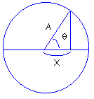
Displacement, velocity and
acceleration are related to each other by frequency.

X = A Cos q
V = dX/dt = d(A Cos q)/dt
= A w Sin q,
Vmax occurs where Sin q =
1
Therefore,
Vpk = A w = A
x (2pf) = (Disp./2) x 2 pf
= pf Disp. (Double Amplitude)
= 3.1416 (CPM/60)(1 inch/1000)
= 52.36 x 10 -6 mils.CPM
Disp.= Vpk / pf
= (1/p)(Vpk/f)
= 0.3183 (Vpk/f)
a = dV/dt = d(A w Sin q)/dt
= d(A 2pf Sin q)/dt
= 2pf V ( - Cos q),
apk = 2 pf V (
-1)
[The (-) means that g is 180 deg. out of peak with disp.]
G = a / 386.1 = 2pfV / 386.1
= 0.0162 fV (in/second2)
(1) Vibration in Cooling
Tower: A cooling tower contains essentially 3 pieces
of rotating machinery - the motor, the gear reducer
and the fan. The primary forces which would cause an
increase in vibration level include;
- ● The vibration of the fan
and fan shaft is caused by the fan unbalance (1 x
rpm), blade pass frequency (number of blades x rpm),
fan shaft misalignment (2 x shaft rpm), fan bearings
(more than 10 x shaft rpm)
- ● The motor and drive shaft
i.e. motor or drive shaft unbalance (1 x drive shaft
rpm) or misalignment (2 x drive shaft rpm)
- ● The gear reducer itself
- bearings (more than 10 x shaft rpm), gear mesh (number
of teeth x rpm)
Of course, if there is a
blade resonance or structural resonance which corresponds
to one of the frequencies noted above, then a relatively
small force can create a high vibration. In this case,
since there is almost always some unbalance and misalignment
present, the problem would be the presence of a resonance
rather than too much unbalance, etc. In either case,
of course, the electronic switch would trip.
(2) Location and Number of
Vibration Switches: Most often only one switch is used.
However, some customers use two, one on the motor and
one on the gear reducer. When only one switch is used,
the preferred location is on the side of the gear reducer.
Since Vibration Switches measure the vibrations perpendicular
to its base, the advantage of this location is that
we will be sensing the radial vibration from both the
fan shaft and the coupling shaft.
The vibration switch will
then sense the vibration resulting from unbalance and
misalignment of fan shaft and blade pass frequency,
plus unbalance and misalignment of the coupling shaft.
(Since these potential faults generates vibrations at
different frequencies, it is essential that the switch
trip on vibration velocity.) Further, protection is
also afforded in the gear reducer itself.
In the past, some cooling
tower manufacturers have mounted the switches on the
motor rather than the gear reducer. This will protect
for motor and coupling shaft unbalance. On wooden structures
which are relatively soft, a severe fan unbalance may
be sensed at this location (i.e. severe damage may result
before a trip occurs) and affords no protections for
the gear reducer. However, with a concrete structure,
it is unlikely that fan vibrations would be sensed at
the motor location.
The motor location was chosen
for convenience when only mechanical type vibration
switches were available. These required reset to be
accomplished with a reset button on the vibration switch
itself and it was inconvenient to get to the gear reducer
to accomplish reset. Since the electronic type of vibration
switches provide the capability for latching the trip
and remote reset, when a trip occurs, it is not necessary
to get to the gear reducer in order to reset the switch.
A reset button could be located at the motor platform
or other convenient location.
(3) Benefits of Electronic
Switches over Mechanical Switches: Historically, users
have specified mechanical vibration switches (like Murphy
VS-2EX series vibration switches) because there have
not been alternative and the limitations of mechanical
switches have not been widely disseminated. The electronic
switch has been in use for several years but is still
not widely known. The mechanical switch is relatively
cheap but is relatively ineffective and undependable.
There are several fundamental reasons for this resulting
from the inherent limitations of mechanical switch.
Yet strangely, acceleration switches are used on many
cooling tower fans. They may be effective with severe
gear problems but not for drive shaft misalignment and
unbalance or fan unbalance. A velocity sensitive device
is appropriate for gear reducers. A careful look at
how each type device operates and performs may help
you to understand its capabilities and make the proper
choice for his equipment protection needs.
Many large diameter cooling
tower fans have inadequate vibration cutout devices.
Devices designed for other applications, such as mechanical
inertia spring or magnetic release - switches are often
in use. Cooling tower fans up to 30 feet in diameter
should have a system that can respond in a linear manner
to preset vibration severity levels over a frequency
range from 120 to 30,000 cycles per minute. Provisions
for a time delay to avoid start-up trip out are also
important.
These requirements are beyond
the capability of most mechanical devices. Such devices
set to trip on one frequency range may not respond to
low frequency vibrations. It is also common to find
that in order to prevent them from tripping out on startup,
mechanical devices are set so high or are so remotely
located as to be ineffective. Mechanical devices are
also of no use in establishing monitoring systems.
Mechanical Vibration Switch,
by its nature is acceleration sensitive. In principle
a magnet exerts a pulling force on a weighted arm. This
force is opposed by an adjustable spring by which the
operator sets the trigger level-the greater the spring
force, the less the acceleration force required to overcome
the spring. When the acceleration force exceeds the
magnetic force, the latching magnet pulls in the arm
and mechanical relay is thus closed, proving the alarm
or shutdown.
Electronic vibration devices
that monitor vibration levels based on velocity measurements
are available to meet requirements of large diameter
cooling tower fans. However, a careful examination of
their frequency response is required to assure protection
at the large fan's lower operating speeds. Fans larger
than 30 ft operate at speeds that are below the useful
range of most velocity-limiting systems. These larger
fans should have a system that reacts to displacement
measurements to monitor fan conditions. Systems based
on proximity sensors are best suited for this application.
Electronic Vibration Switch
consists of a solid state crystal which produces electrons
when it is deformed by the acceleration force. This
electrical output is electrically integrated, producing
a signal proportional to velocity. This signal is then
compared with a preset limit and triggles a triac (in
effect a solid state relay) if the level has been exceeded.
This relay closure can be used by the customer to alarm,
shutdown, etc. Thus it is a completely solid state,
self contained unit. The customer need only bring 110
V power leads to it and bring leads to the relay.
Inputs from major users are
that the mechanical switch frequently triggers when
it shouldn't during its youth, and may not trigger at
all after it has been installed for some time. (One
year after installation.) Very frequently the user has
jumpered them out. In short, as a protection device,
they're very questionable indeed! Why?
- ● They are mechanical and
subject to corrosion, dirt, etc. (The electronic unit
is all electronic - no moving parts.)
- ● The mechanical construction
is a very undesirable approach from a vibration viewpoint
- the cantilevered beam, mass, and springs are subject
to resonance being excited by higher frequency machinery
vibration (which may be one reason for spurious triggering.)
- ● The mechanical switch
triggers proportional to acceleration. Damage potential
is proportional to velocity in the speed ranges of
most rotating machinery. The damage potential to your
auto is very high at 60 MPH and zero acceleration.
Likewise one could have a very high acceleration from
0 to 5 MPH but the damage potential would be relatively
low at this low velocity.
Further, acceleration increases linearly with frequency
(RPM) as compared to velocity. Thus, the amount of
protection depends on frequency and the device gives
too much protection at some frequencies and not enough
at others.
- ● The accuracy of the triggering
point is very poor with the mechanical switch - +/-
5% of full scale. Full scale for the mechanical switch
is 4.5g which means accuracy is +/- 0.22g. This is
a Catch 22, because typically desired limit levels
are around 0.2g. So in this case triggering theoretically
could occur anywhere from zero to 0.4g - very poor
by anyone's standards. (The electronic switch is +/-
10% of set point, i.e. set at 0.2 in/sec velocity,
triggering will occur at 0.2 +/-0.02.>
The solid state of electronic
vibration switch has many advantages over the older
mechanical design as follows;
- ● Electronic switch uses
a crystal to generate and electrical output to sense
vibration level. No moving parts to wear or resonate.
By contrast the mechanical switch uses magnets and
springs to sense the vibration.
- ● Built-in field adjustable
time delay to avoid trip on high start-up vibrations
or from transient vibrations during normal running.
Mechanical switches do not have time delay. Consequently,
trip points are frequently set so high that no protection
is provided.
- ● Trips on velocity rather
than acceleration. The mechanical switch can trip
only on acceleration. All authorities in the field
agree that damage potential is related to vibration
velocity. Acceleration trip provides over protection
to fault which generate high frequency vibrations
(i.e. false trip) and under protection to low frequency
problem (i.e. they do not trip when a low frequency
fault occurs.).
- ● Calibrated setpoint dial.
Permits setting trip level to known value in engineering
units of in/sec. The user never knows where the mechanical
switch has been set, or if it has been re adjusted
by an unauthorized person.
- ● Many options are available
with the electronic switches that are not possible
with the mechanical type switch including: separate
transducer, dual trip settings and 4-20 mA analog
output.
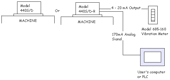
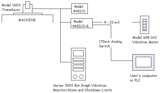
(4) Layout of Vibration Switch
Arrangement
(A) Direct Mounting or With
Remote Readout Option

(B) Remote Transducer Option
or With Remote Readout Option or Remote Control

|


