|
2) Multi-Speed Fan Control
It is possible to further
reduce total annual energy consumption by the fan drive
equipment, but over a wider range of wet-bulb temperature
conditions. To do so requires increased operational
flexibility of the tower. Thus the specification of
multi-speed motors must be considered. The most commonly
used such motors in cooling towers are of the two speed
type with either 4/8 pole or 4/6 pole. Such motors are
capable of operation at full and half speed (4/8) or
full and two-thirds speed (4/6).
The majority of cooling tower
installations incorporate multi speed fan drive motors.
These, all too often, operate the fans throughout the
year in accordance with ambient wet bulb temperature,
heat load capacity, or required cold water temperature.
Without a special additional cost, the energy conservation
is very large if the speed selection is automatically
controlled by using a microprocessor or the operator
has full control discipline. This control is most effective
to apply to the cooling towers having 3 or more cells
installations.
It must be pointed out that
the yearly average cold water temperature is approximately
the same, and therefore so is plant production, for
all modes of operation. Obviously then, considerable
thought should be given to several modes of operation
before one is chosen. Again, it must be pointed out,
that the yearly average cold water temperature will
be higher than if the fans had been allowed to run constantly
at full speed. This may reduce plant production somewhat.
The benefits of reduced energy consumption must be weighed
against any loss in production.
To achieve the power savings,
requires continuous monitoring of the cold water temperature
and manual operation of the fans. This may not be practical,
and may reduce the overall cost effectiveness of the
installation. For large, twin and three cell installations
simple direct control by fan thermostats, may be suitable.
Possibly one for each fan or a multiple unit depending
on the range covered, triggered by cold water temperature,
would be suitable.
As with any such system,
safeguards must be built into the thermostat logic to
avoid exceeding the maximum number of starts a motor
may make in any one hour. Such a situation can occur
during fairly stable but fluctuating ambient conditions
especially if the system lag times are small. Further,
if multi-speed motors are considered, care must be taken
to prevent the fan from operating at any of its low
critical speeds. If attention is not paid to this aspect
of design, the fan could suffer damage and possible
complete failure. To assure long fan life, the cognizant
engineer should contact the fan engineer and obtain
the necessary information and recommendations.
Below tables show the trace
of cold water temperature varying per the entering wet-bulb
temperature under the same thermal conditions in the
range (23.4 oF or 13.0 oC) and
the 12.8 degree of constant pitch angle.
|
Cold Water Temperature
Chart At Full Speed (175 HP Motor) |
| WBT
(oF/oC) |
82.4/28.0 |
80.6/27.0 |
78.8/26.0 |
77.0/25.0 |
75.2/24.0 |
73.4/23.0 |
| Airflow
(CFM) |
1063950 |
1063126 |
1061927 |
1061093 |
1060369 |
1059276 |
| Static
Pressure (" Aq.) |
0.482 |
0.483 |
0.483 |
0.483 |
0.484 |
0.484 |
| Exit
WBT (oF) |
102.34 |
101.21 |
100.10 |
99.00 |
97.92 |
96.85 |
| Cold
Water Temp. (oF) |
89.78 |
88.53 |
87.32 |
86.12 |
84.94 |
83.79 |
| Cold
Water Temperature Chart At Full Speed (175 HP
Motor) |
| WBT
(oF/oC) |
71.6/22.0 |
69.8/21.0 |
68.0/20.0 |
66.2/19.0 |
64.4/18.0 |
62.6/17.0 |
| Airflow
(CFM) |
1058455 |
1057691 |
1056996 |
1056416 |
1055336 |
1054628 |
| Static
Pressure (" Aq.) |
0.484 |
0.485 |
0.485 |
0.485 |
0.485 |
0.486 |
| Exit
WBT (oF) |
95.80 |
94.76 |
93.73 |
92.72 |
91.73 |
90.75 |
| Cold
Water Temp. (oF) |
82.66 |
81.54 |
80.45 |
79.38 |
78.33 |
77.29 |
Note that the fan power is
increasing as the ambient wet-bulb temperature entering
into the cooling tower is gradually decreased. This
is due to the decrease in the exit air temperature (increase
in air density and actual static pressure.
|
Cold Water Temperature
Chart At 2/3 Speed (60 HP Motor) |
| WBT
(oF/oC) |
82.4/28.0 |
80.6/27.0 |
78.8/26.0 |
77.0/25.0 |
75.2/24.0 |
73.4/23.0 |
| Airflow
(CFM) |
703842 |
703337 |
702878 |
702483 |
701846 |
701400 |
| Static
Pressure (" Aq.) |
0.215 |
0.214 |
0.214 |
0.214 |
0.214 |
0.214 |
| Exit
WBT (oF) |
110.20 |
109.27 |
108.35 |
107.45 |
106.57 |
104.85 |
| Cold
Water Temp. (oF) |
95.75 |
94.73 |
93.74 |
92.76 |
91.82 |
90.89 |
| Cold
Water Temperature Chart At 2/3 Speed (60 HP Motor) |
| WBT
(?/?) |
71.6/22.0 |
69.8/21.0 |
68.0/20.0 |
66.2/19.0 |
64.4/18.0 |
62.6/17.0 |
| Airflow
(CFM) |
700977 |
700589 |
700250 |
699726 |
699349 |
698993 |
| Static
Pressure (" Aq.) |
0.214 |
0.214 |
0.214 |
0.214 |
0.215 |
0.215 |
| Exit
WBT (oF) |
104.85 |
104.01 |
103.19 |
102.39 |
101.60 |
100.82 |
| Cold
Water Temp. (oF) |
89.98 |
89.08 |
88.21 |
87.36 |
86.52 |
85.70 |
The fan operations can be
controlled to save energy considering the required cold
water temperature above. Of course, the actual cold
temperature could be varied when to operate the fans
below sequence because the isolation of individual cell
air streams is ineffective due to non-partition between
cells. The full speed fans will receive a substantial
amount of air from the cells that are OFF or at 2/3
speed due to the differential pressure between cells.
| Entering
Wet-Bulb Temperature |
Fan
Operation Modes |
Total
HP/Energy Saving |
| 80.6
oF(27.0 oC) |
all
fans at full speed |
Total
838.8 / 0% |
| 78.8
oF(26.0 oC) |
5
fans at full speed and 1 fans at 2/3 speed |
Total
640.2 / 23.7% |
| 77.0
oF(25.0 oC) |
4
fans at full speed and 2 fans at 2/3 speed |
Total
540.9 / 35.5% |
| 75.2
oF(24.0 oC) |
3
fans at full speed and 3 fans at 2/3 speed |
Total
441.6 / 47.4% |
| 73.4
oF(23.0 oC) |
2
fan at full speed and 4 fans at 2/3 speed |
Total
342.3 / 59.2% |
| 71.6
oF(22.0 oC) ~ 59.0 oF(15.0
oC) |
all
fans at 2/3 speed |
Total
243.0 / 71.0% |
3) Variable Speed Fan Control
The most efficient method
of energy saving is obtained by varying the speed of
driven machine. The speed of motor shall be automatically
adjusted by the use of adjustable frequency power. A
variable frequency controller simulates the normal AC
voltage sine wave. The adjustable frequency drive converts
60 hz (or 50 hz) power to 0 - 100 hz power which, when
frequency controlled, determines the synchronous speed
of the standard induction fan motor. This is accomplished
with solid state electronics. Any standard AC fan motor
may be speed regulated, manually or automatically, in
the 0 - 60 hz speed range for air flow rate control.
It is obvious that the power
could be most significantly saved with the variable
speed control. However, most careful consideration does
need to be given to the resonant or critical speed of
the fan assembly. That is, one would not like to operate
the fan for any length of time at its critical speed
which might cause damage. Due to these dynamic characteristics,
cooling tower fans are not suitable for variable speed
service. Of course, the motor speed is restricted with
the minimum speed (generally 500 to 600 RPM) of gear
reducer, since the internal parts including the bearings
can not be lubricated at the low speed.
4) Variable Pitch Control
The previous discussion was
based on the adjustable pitch fan, which is delivering
a constant amount of air flow at the preset pitch angle
and the pre-selected fan speed. Power consumption changes
only with changes in air density. The previous tables
show the actual fan power is varying the ambient wet-bulb
temperature. This is only due to the changes in the
air density.
The pitch of variable pitch
fan is automatically changed in operation as per the
heat loads and air density. This fan provides the precise
amount of airflow to control the outlet cooling water
temperature and save substantial amounts of energy at
the same time. In the years of low energy cost, the
impetus to use the variable pitch fans has been for
precise temperature control, generally to within four
percent or less of the set point. However, there is
new interest in variable pitch fans for the energy saving
potential as well.
Another one of the major
advantages of the variable pitch fan is constant speed.
Constant speed control eliminates the problem if the
fan speed is at least ten (10) percent away from a critical
speed and also eliminates the frequent stopping and
starting normally associated with manually pitched fans
under fluctuating loads. This constant speed increases
the service life of drive components such as motors,
couplings and gear reducers. The inrush current when
starting the standard fan motor is usually 600 - 700%
of full load current. This means that the motor will
experience 6-7 times the normal mechanical stresses
and approximately 36 times the normal heating during
the starting period. If the starts are frequent and/or
prolonged due to the fan inertia, the motor will fail
prematurely. This is due to the break down in electrical
insulation caused by these abnormal thermal/mechanical
stresses. This same peak stress is also transmitted
through out the coupling shaft and the gear reducer.
This cyclical stress pattern will eventually reduce
the fatigue life of these components.
An automatically adjustable
pitch fan is a very simple mechanical device. The blades
are attached to cammed shafts which are rotated through
a ring when a central actuating rod is moved up and
down. A main load spring moves the rod upward and compressed
air, operating against a diaphragm, overcomes the spring
pressure and moves the rod downward. Compressed air
is introduced to the diaphragm by a rotating air union.
A force diagram is shown in below.
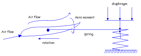
As the blade moves the air,
the aerodynamic moment (clockwise) tries to feather
the blade. The hub spring creates an opposing moment
(counter clockwise) to make the blade do work. This
is a fail safe mechanism so that if the air pressure
on the diaphragm fails, the fan operates as a fixed
pitch fan providing design air flow. Fans can be assembled
to move to maximum or minimum air flow on loss of air
signal. The initial spring preload has to be sufficient
to keep the blade from feathering.
To reduce the air flow, or
even reverse the air flow direction, air pressure is
exerted on the diaphragm to oppose the hub spring and
decrease blade pitch. When the blade pitch is about
minus 10o, no work is done and essentially
"zero" flow is attained. Minimum air velocity
obtainable is approximately 50 - 100 fpm. If the hub
has its pitch stops adjusted for reverse flow, the air
is directed downward and can be as much as about 60%
of the upward flow at the same horsepower. The decrease
in flow capability is because of poor efficiency in
the reverse pitch mode.
A typical fan hub mechanism
consists of Hub Spring, Diaphragm, Piston, Blade shafts
with eccentric actuator, Rotary air joint, Valve positioner,
etc. The blade shafts or axles hold the fan blade and
have an eccentric engage the groove in the piston. As
the piston moves up or down a twisting motion is imparted
to the blades, changing pitch. The rotary air joint
is the static/dynamic interface between the rotating
fan and its control air system.
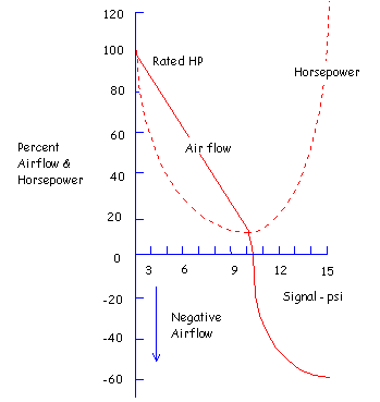
A typical variable pitch
hub requires a 3- 15 psi control signal and operates
the blades from some maximum pitch down to "zero"
air flow. It typically fails to maximum flow if the
control signal is interrupted but can be made to fail
to minimum or negative flow. Most hubs are capable of
45o total pitch travel and perform as shown
in below figure.
To be continued. Please press the next button....
|


