|
1) General
As a highly visible tower
component, the fan cylinder is often one of the finest
targets for cooling tower modernization. The cylinder
allows only moderate fan efficiency and elevation of
the discharge air stream to help reduce recirculation.
Such cylinders were normally constructed of concrete,
wood or steel which precluded the construction of optimum
cylinder shape. The development of modern GRP or FRP
cylinders has allowed to design for maximum fan efficiency
and for minimum discharge air recirculation. Cylinder
design may be looked at as having three separate and
highly important components;
- ● Fan Cylinder Entrance
Section
- ● Fan to Cylinder Tip Clearance
- ● Velocity Recovery Section
As air is induced out of
the plenum chamber beneath the fan, it tends to follow
very predictable streamlines into the fan cylinder.
As the air moves into the cylinder, a well-defined vena
contracta develops (The point at which the flow area
reaches its minimum is called Vena Contracta). This
vena contracta actually defines the ideal shape of the
fan cylinder as well as the optimum elevation of the
fan in the cylinder. It is obvious that a fan located
in the straight sided cylinder depicted in Figure A
cannot possibly operate at full efficiency for three
reasons;
- ● The fan tips, which represent
a very high percentage at the fan disc area, are operating
outside the vena contracta in a region of low air
flow.
- ● The area between the cylinder
wall and vena contracta develops high turbulence which
further increases pressure losses and reduces fan
efficiency.
- ● The location of the fan
is so low in the cylinder that the air approaching
the blades has not had a chance to straighten and
is attacking the blades at an angle.
An energy loss occurs as
the fan blades must turn the air, resulting in further
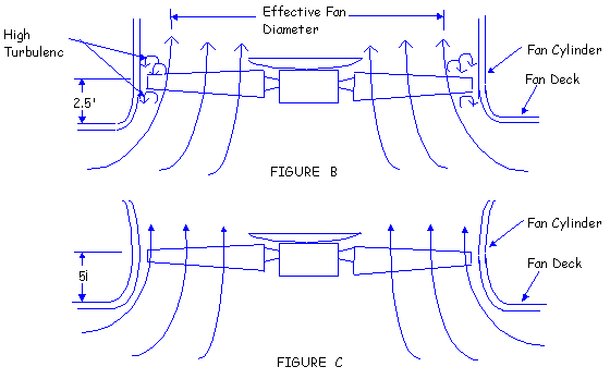
efficiency degradation. Figure B depicts a more common
cylinder that is an improvement over the straight-sided
cylinder, but is far from optimum. This cylinder only
partially recognizes the vena contracta? effect of reducing
the effective diameter of the fan disc. The fan tips
are operating in the low velocity, high turbulence zone
and the angle of attack between the streamlines and
fan plane is not vertical.


The ideal cylinder entrance
and fan elevation design is shown in Figure C. This
inlet produces minimum turbulence and pressure losses
by following the natural shape of the discharge jet.
The cylinder, in this design, confirms to the flow path
that the air is attempting to take as it exits the tower.
Note also that this cylinder properly locates the fan
plane at a significantly elevated position, assuming
that the air streamlines are vertical before they cross
the plane of the fan disc.
An example of the relative
performance between the optimum cylinder entrance in
Figure C and cylinder shown in Figure B helps put the
value of careful system design into perspective. A 22
feet diameter cooling tower fan may typically be required
to move 700,000 CFM against a pressure drop of 0.40
inch H2O. The CFM required is fixed by the
cooling tower thermal duty and is the same regardless
of cylinder design. The cooling tower system operation
lines assume identical louver, fill, eliminator and
plenum configurations - only the cylinders are different.
The fan horsepower required to move 700,000 CFM is 119
BHP with the optimum configuration (Figure C) and 136
BHP with the improved, but not ideal design (Figure
B). This is an important analysis for the project owner
to consider whenever fan cylinder replacement is called
for. Not all "modern" fiberglass cylinders
allow the fan to perform at peak efficiency. Unless
the cylinder manufacturer or the owner has the capability
of analyzing the relationship between cylinder and fan
design, significant operating savings can be overlooked.
Once the air is properly
directed into the cylinder, maintenance of close tip
clearance becomes the next consideration. The greater
the dimension between the fan tip and the fan cylinder,
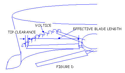
the less efficient the fan. Space between the fan tip
and cylinder allows the creation of air vortices at
the blade tips which shorten the effective length of
the blade, reducing fan performance. (Figure D)

Close tolerance between the
blade tip and fan cylinder minimizes the magnitude of
these disturbances, maximizing fan performance. For
various, practical reasons, tip clearance must be greater
than "zero" to accommodate wind-induced deformation
of the cylinder, thermal expansion of the fan blade
and the possible build-up of ice inside the cylinder
under reverse flow conditions. Tip clearances of two-inch
to three inch are not uncommon in cylinders designed
without sufficient wind load capability, or without
close attention to production and construction details.
The performance difference
(in terms of horsepower) of a 22 feet diameter fan with
a reasonable tip clearance, is approximately 4.5%. This
makes it obvious that the tip clearance of a replacement
design is critical. Much of the benefit obtained by
utilizing a properly-eased cylinder inlet design can
be lost if tip clearance is not rigidly controlled.
Excessive tip clearance is usually the result of poor
workmanship, poor fit-up, or inadequate structural design.

The next important aspect
of good cylinder design is provision for a velocity
cone. The addition of the velocity recovery cone to
a fan cylinder is in recognition of the fact that the
total energy (T) of a moving air stream is constant
at all points except for viscous and turbulence losses.
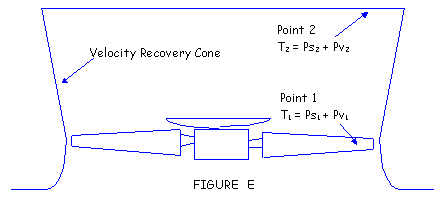
Total energy is the sum of the static pressure (Ps)
and the velocity pressure (Pv) at a given point. Referring
to the fan system shown Figure E, the total energy of
the stream immediately above the fan (point 1) is: T1
= Ps1 + Pv1. The total energy
at the fan cylinder discharge (point 2) is: T2
= Ps2 + Pv2. If L represents losses
due to turbulence and drag between point 1 and point
2, and Ps2 is atmospheric pressure, assumed
equal to zero:
T1 = T2
+ L
Ps1 + Pv1 = Ps2 + Pv2
+ L
Ps1 = (Pv2 - Pv1) +
L
Since the velocity cone reduces
the velocity of discharge air stream. Pv2
is less than Pv1. This means that relative
to atmospheric pressure, the static pressure at a point
just above the fan becomes more negative when the recovery
cone is added. In other words, the pressure against >
which the fan operates has been reduced, allowing the
fan to move the rated CFM at lower consumed horsepower.
The loss (L) keeps the recovery from being complete.
A common rule of thumb is that 70% of the difference
in velocity pressure (Pv2 - Pv1)
is recovered in the recovery cone portion of the cylinders.
In actuality, this percentage may vary from 50% to 95%,
depending on fan operating conditions.
If a 14 foot high velocity
recovery cone is added to the ideal cylinder shown in
Figure C, the horsepower required to move 700,000 CFM
against 0.40?H2O static pressure is further
reduced from 119 BHP to 99 BHP. This represents an additional
saving in the power consumption.
An important system consideration
sometimes overlooked when increasing fan cylinder height
is the impact that the taller stack has on the structure.
The taller stack imposes greater dead loads, present
a greater projected surface-to-wind loads and has more
mass to respond to seismic acceleration. These loads
must be handled in a cooling tower structure which may
not be equipped with sufficient bracing to accommodate
added stress.
|


