2) Effect of Velocity Recovery
In the case of Wet Cooling
Towers, a relatively common means of improving inlet
conditions and conserving horsepower is known as a velocity
recovery stack. These stacks incorporate a slightly
tapered exit cone and a well rounded inlet bell. In
theory, there is a significantly reduced velocity pressure
at the exit compared to the plane of the fan. Since
the quantity of air is the same at both planes, the
recovery of velocity pressure is converted into "static
regain" which lowers the total pressure requirements
of the fan, thus saving horsepower.
Certainly, any axial fan
with a velocity pressure of 0.3 inches Aq. or greater
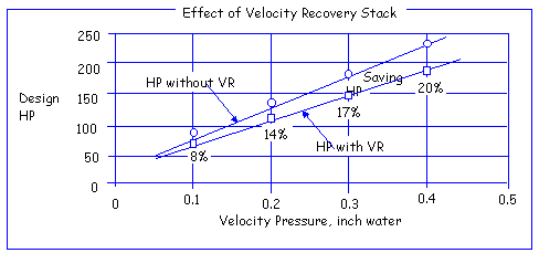
can benefit from a fan stack. Below figure shows the
effect of fan stack and its potential savings of horsepower
from a system efficiency standpoint. Omission of fan
stack would be a loss. Note that the fan stack effect
is more pronounced at the higher velocity pressures
and the horsepower saved at higher flows is very significant.
The entrance into V.R. stack through the fan deck should
not be ignored as often, it in itself creates turbulence
and losses. Although the stack design usually incorporates
a generous inlet radius, a sharp corner through the
fan deck or heavy structural members beneath can sometimes
negate the smooth air flow condition in the stack itself.

The power absorbed by the
fan can be reduced by this pressure recovery. Particularly
in the case of cooling towers in which the fan velocity
pressure is very high in comparison with the static
pressure, much attention is directed toward the gradual
reduction in air velocity from fan plane to the discharge
plane of fan stack. The resultant reduction in the exit
air kinetic energy results in substantial power saving.
Basically,
Hudson assumes 7 degree of angle per side and an efficiency
of recovery of 70%. A poorly designed fan stack is a
potential cause of poor air distribution, low fan stack
efficiency and significant vibration due to the resonant
frequency of fan. For high velocity designs the normal
height of fan stack and the diameter of fan ratio is
from 0.6 to 1.0.
VP Recovery = Stack Effi.
x (VP Fan - VP Stack Top)
where, Stack Efficiency :
70%, VP Fan = Velocity Pressure at Fan
Air Velocity
1
V.P. act. = [ --------------------- ]2 x
----------------------(inch Aq.)
4008.7
Density Ratio
(A "4008.7"
is a coefficient for converting all the used units to
inch water.)
V.P. = (1/2) x (density
acceleration of gravity) x V2
= (1/2) x (0.075 lb/ft3 115,820 ft/min2)
x V2 (ft/min)2
(1 lb/ft2 = 0.1922 inch Aq.)
= 0.1922 x (1/2) x (0.075 115,820) x V2
= V2/ 16,069,372.18
= [V/4008.7]2 inch water
Airflow Rate (acfm) at Fan
Air Velocity = --------------------------------------------
(ft/min)
Net Fan Area
0.075
Density Ratio = ------------------------------
Air Density at Fan
VP stack top = Velocity
Pressure at stack top
Air Velocity
1
V.P. =[ --------------------- ]2 x ----------------------
(inch Aq.)
4008.7
Density Ratio
0.0750
Density Ratio = -------------------------
Exit Air Density
Airflow Rate (acfm) at Stack Top
Air Velocity = ------------------------------------------------------
(ft/min)
Stack Top Area
Fan Stack Top Diameter
= Fan Diameter + [ 2 x (Tan 7o x Venturi
Height) ]
Fan Stack Top Area = (pie/4)
x {(Stack Top Diameter)2 }
Net Fan Stack Top Area
= (pie/4) x {(Stack Top Diameter)2 - (Seal
Disc)2}
(Note: Hudson is not considering
the no air flow zone at the top stack due to the seal
disc. Refer to figure shown in the paragraph of Flow
Pattern. Unless the height of fan stack is as mush as
the fan diameter the fan stack top area must subtract
the area of seal disc in the fan.)
Venturi Height = Height
from fan plane to top of stack
Suppose airflow volume is
1,063,126 acfm, fan diameter is 28 feet, the height
of venturi is 6.0 ft, and air density at fan inlet is
0.0688 lb/ft3. What is the velocity recovery?
ACFM
Velocity at fan = -------------------------------------------------------------------------
(pie/4) x (Fan Diameter2 - Seal Disc Diameter2)
1,063,126
= ---------------------------------- = 1,853.71 FPM
(pie/4) x (282 - 7.3332)
1,853.71 0.0688
V.P. at fan = [--------------]2 x -------------
= 0.1963" Aq.
4,008. 7
0.0750
Fan Stack Top Diameter =
28' + 2 x (0.12278 x 6.0) = 29.47 ft
Fan Stack Top Area = (pie/4) x 29.472= 682.1
ft2
ACFM
1,063,126
Velocity at stack top = ----------------------------
= ----------------- = 1,558.60 fpm
Stack Top Area
682.1
1,558.60
0.0688
V.P. at stack top = [ --------------- ]2
x ------------- = 0.1387" Aq.
4,008.7
0.0750
Acc'ly. the velocity recovery
= 0.7 x (VP fan - VP stack) = 0.7 x (0.1963 - 0.1387)
= 0.0403" Aq.
While,
the velocity recovery in case of considering the dead
zone in the top stack is 0.0271" H2O.
(Net fan stack top area: 640.03 ft2, velocity
pressure at stack top: 0.1576") The difference
in the static pressure gain affects directly the deviation
in the fan brake horsepower. In case of this particular
sample job (0.4825" Aq. of static pressure), the
fan brake horsepower per Hudson fan rating sheet is
smaller than one per above normal procedure by 3.1 HP.
Of course, the velocity recovery can be varied person
by person since the efficiency of fan stack, the angle
of fan stack and fan tip clearance, etc. can differ
from above. So, we recommend to use your own procedure
in calculating the velocity recovery. In general, there
is no need to input the value of venturi height to the
fan rating program if the venturi height was actually
considered at thermal design stage. Note that there
are some differences in calculating the velocity recovery
between Hudson and our conception. For your information,
the actual total pressure could be expressed as follows;
Actual
Total Pressure = Act. Static Press. + Act. Velocity
Press. - Velocity Recovery (inch Aq.)
3)
Flow Pattern
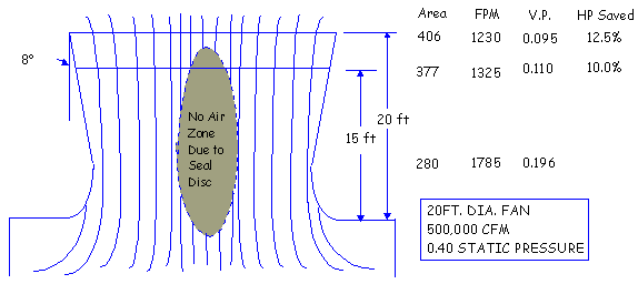
The
below figure shows pictorially the flow condition which
exist through the fan and recovery stack. Note the very
streamlined flow which would be possible with a fully
faired hub, and the actual flow around a typical hub
seal. The information given in below figure is for a
no wind condition. If a 15 MPH wind will give the discharged
air an angle of about 45o and cause flow
separation on the upwind side of the stack. Under this
condition the velocity pressure recovery may be practically
nullified.

|


